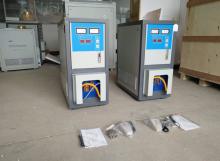
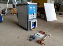
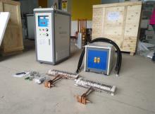
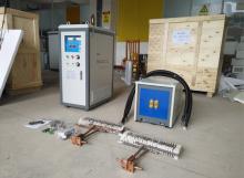
Induction heater is also called induction heating power supply, also known as induction heating equipment. It is a collective term for induction heating of all workpieces to be heated, including induction heating power supply and induction heating equipment.
As the saying goes, do it yourself. I believe many friends like to make some homemade gadgets. But I don't know if you have tried making a small device like induction heating by yourself. So how to make an induction heater and what kind of steps are needed? Let's take a look.
1. Cost estimation:
Copper tube and copper strip: 210 yuan;
Two EE85 thickened cores: 60 yuan;
3 high-frequency resonance capacitors: 135 yuan;
Bakelite board: 60 yuan;
Water pump and PU pipe: 52 yuan;
PLL board: 30 yuan;
GDT board: 20 yuan;
Power board: 50 yuan;
MOSFET: 20 yuan;
2KW voltage regulator: 280 yuan;
Heat sink: 80 yuan;
Total: 997 yuan
2. Overall structure:
Series resonance 2.5KW phase-locked loop frequency tracking ZVS, MOSFET full-bridge inverter; two-speed impedance conversion of magnetic core transformer, water-cooled heat dissipation, mains auto-voltage regulation, bus over-current protection.
Before starting production, it is necessary to clarify some basic principles and concepts, so as not to be confused.
1. Heating mechanism
① Eddy current. As long as the metal object is in the alternating magnetic field, it will produce eddy current. The powerful high-density eddy current can quickly heat up the workpiece. This mechanism exists in all conductors whose resistivity is not infinite.
② Induction circulating current. The workpiece is equivalent to a short-circuited 1-turn coil, and the induction coil constitutes an air-core transformer. Since the current ratio is equal to the inverse ratio of the turns ratio, the current on the workpiece is N (number of turns) times the current in the induction coil. The induction short-circuit current makes the workpiece heat up rapidly. This mechanism exists in any conductor. In the case of constant magnetic flux density, the larger the area of the workpiece perpendicular to the magnetic field vector, the greater the current induced on the workpiece, and the higher the efficiency. It can be seen that a workpiece with a large magnetic flux cutting area is easier to obtain a high temperature than a workpiece with a small area.
③ Magnetic domain friction (there are countless small areas in ferromagnets that have been magnetized with a line degree of about 10-4m. These small areas are called magnetic domains). The magnetic domains of ferromagnetic materials are magnetized in an alternating magnetic field. Under the action of the inverse magnetic ring, it rubs violently and generates high temperature. This mechanism is dominant in ferromagnetic materials.
It can be seen that the heating effect of workpieces of different materials is different because of the different heating mechanisms. Among them, the three mechanisms of ferromagnetic materials account for the best heating effect. When the ferromagnetic substance is heated above the Curie point, it becomes paramagnetic, and the magnetic domain mechanism decreases or even disappears. At this time, the remaining two mechanisms can only be used to continue heating.
When the workpiece crosses the Curie point, the magnetic induction phenomenon is weakened, and the equivalent impedance of the coil drops greatly, causing the current of the resonant circuit to increase. After crossing the Curie point, the inductance of the coil also decreases. The natural resonant frequency of the LC circuit will change. The heater of the fixed excitation method is detuned and the equipment is damaged or the efficiency is greatly reduced.
2. Why use resonance? Which resonance should be used?
① Answer the first question first. We used to think that as long as a strong enough current is passed into the induction coil, it will become an induction heating device. We also did an experiment on it.
There is indeed a heating effect in the experiment, but it is far from achieving the desired effect of the output power of the power supply. Why is this? Let's analyze it. Obviously, for a fixed workpiece, the heating effect is proportional to the actual output power of the inverter. For the induction coil, it is basically pure inductive, that is, the current change during it always lags behind the change of the voltage at both ends, that is to say, when the voltage reaches the peak value, the current has not reached the peak value and the power factor is very low. We know that power is equal to the overlap area of the voltage waveform and the current waveform. In the inductor, the current and voltage waveforms are staggered by an angle. At this time, the overlap area is small. Even if a huge current passes through it, it is useless. This is if P=UI is simply calculated, only reactive power will be obtained.
On the other side, the current in capacitors always leads the voltage change. If the capacitor and the inductance form a series or parallel resonance, one is ahead and the other is lagging, and it just cancels out at resonance. Therefore, the capacitor is also called a power compensation capacitor here. At this time, from the perspective of the excitation source, it is equivalent to supplying power to a pure resistive load, the current waveform and the voltage waveform are completely overlapped, and the maximum active power is output. This is the main reason why series (parallel) compensation capacitors are used to form resonance.
② The second question, LC resonance has series resonance and parallel resonance, what structure should be used?
To put it bluntly, in parallel resonant tanks, the resonant voltage is equal to the excitation source voltage, and the current in the tank circuit (TANK) is equal to Q times the excitation current. The tank circuit current of the series resonant circuit is equal to the excitation source current, and the voltage at both ends of L and C is equal to Q times the excitation source voltage, each has its own merits.
From the circuit structure point of view:
For constant voltage source excitation (half bridge, full bridge), a series resonant circuit should be used, because the supply voltage is constant, the larger the current, the greater the output power. For the series resonant circuit, the impedance of the entire circuit is the smallest at the resonance point, while the resonance current also reaches the maximum value, and the maximum power is output. At the time of series resonance, the Q value of the no-load circuit is the highest, the voltages at both ends of L and C are higher, and the tank circuit current is wasted on the circuit resistance, and the heat is huge.
For constant current source excitation (such as a single-tube circuit), parallel resonance should be used. The voltage at the LC terminal is very high during free resonance, so a large power can be obtained. Parallel resonance has a very important advantage, that is, the loop current is the smallest when there is no load, and the heating power is also very small. It is worth mentioning that from the experimental results, the same resonant capacitor and heating coil, the same driving power, parallel resonance is suitable for heating larger workpieces, and series resonance is suitable for heating smaller workpieces.
3. production
After understanding the above principles, we can start to build our induction heating equipment. The equipment we made is mainly composed of voltage regulating rectifier power supply, phase locked loop, dead time generator, GDT circuit, MOS bridge, impedance transformation transformer, LC tank circuit and heat dissipation system.

 en
en  cn
cn  jp
jp  ko
ko  de
de  es
es  it
it  ru
ru  pt
pt  th
th  vi
vi  pl
pl 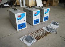



 Call us on:
  Email Us:
  NO. 688th South Baoguang Road, Xindu District, Chengdu City, Sichuan Province, China